Back in July of 2021, I had the pleasure of building the beautiful Lego Ideas Typewriter 21327. It’s a stunning model typewriter, approximately half scale, that has occupied a feature space on my office desk ever since I completed it.
The action of the typewriter is truly satisfying, and even though all of the keys cause the same hammer to actuate, the way that the carriage moves from right to left as you type really sells the effect.
The first part of the build was repetitive, as there are two very similar mechanisms that make up each of the actuating keys. It took awhile to make these, and it was difficult at this stage to understand how these pieces fit into the finished project, but I got through the grind with the help of a podcast.
Soon enough, I could mount all of the key lever arms into a grid pattern and arrange them in the frame that makes up the back plane of the keyboard for the typewriter.
Next up was the hammer mechanism, a wide bar that is pushed forward any time one of the keys is pressed down. As mentioned above, every key on typewriter that can be actuated causes a single shared hammer to spring forward. Although it would have been nice to have distinct hammers for each key, I don’t think that it would have been possible at this scale.
In front of the hammer mechanism is a flat smooth track that the carriage slides on. In this model, the carriage is made up of a movable wheeled component that can move from left to right on that smooth track, actuating a ratchet system that prevents it from sliding back to the left. Whenever a key is depressed, the ratchet lifts and the carriage moves one notch back to the left.
With the guts of the model complete, it was time to turn start building the body that contains the inner workings.
The seafoam green colour of the body components is striking, although I’ll admit that I had difficulty differentiating it from Technic grey at times, causing me to mix up some internal and external parts. I didn’t notice the mistake until much later in the build, and had to backtrack to fix it. Being colour blind can be a chore at times.
This model is gorgeous. It looks great on my desk, and I’ve had co-workers on Zoom calls ask if it is a real typewriter. I had fun building it, and love to watch the mechanism at work. I’d call this set a must-have for any fan of Technic and of typewriters.
In the first post in this series, I documented the process of procuring new media server hardware, installing and configuring the operating system, and getting my Drobo shares mounted with systemd and cifs.
I tend the run the services that are hosted on my media server inside of Docker containers. The advantage to this approach is twofold:
If anything stops working, I can just restart the container
Configuration can be kept in one location, mounted by the container, and backed up to my Drobo so that I can easily recover in case of hardware failure
When setting up a new media server, I typically create a docker-compose file that lists all of the containers that I’d like to run. The Docker files that describe each container come courtesy of linuxserver.io, which provides an excellent collection of containerized services. Each container’s README.md file contains a sample docker-compose file that shows how to configure the service. Here’s the docker-compose file for linuxserver/plex:
I make use of the PUID and PGID environment variables to configure which user account this container runs as, and set it up to mount all of the media shares that Plex will serve.
Once I have added all of my services to a single docker-compose file, I use systemd to define a service that runs docker-compose up when the system boots:
This service runs at boot after the Docker daemon has started, the server has obtained an IP address, and the Drobo share that contains my media has been mounted. For more information on how I mount my media shares, see the previous post in this series. The only other part of this service that needs to be customized is the WorkingDirectory attribute, which needs to be set to the path to the directory that contains the docker-compose file.
With these files in place, I can enable my new service:
$ sudo systemctl enable docker-compose.service
reload the systemctl daemon so that it picks up the service definition:
$ sudo systemctl daemon-reload
and give it a test run:
$ sudo systemctl start docker-compose.service
At least, that’s how it’s supposed to work. When I set Plex Media Server up using this approach, it didn’t start. In fact, it didn’t even try to start because my new service required docker.service, which didn’t exist. It turns out that modern Ubuntu distributions have repackaged a bunch of common services as “Snaps”, and that those Snaps have different names than their non-Snap counterparts. In this case, docker.service had been rebranded as snap.docker.dockerd.service, which is clearly an improvement.
Lesson learned, I tweaked my service definition to use the correct identifier for the Docker daemon and tried again. This time, the service tried to run docker-compose up, but failed with a permissions error:
ERROR: .FileNotFoundError: [Errno 2] No such file or directory: './docker-compose.yml'
I did some digging and found that I could once again invite the “Snap” edition of Docker to The Accusing Parlor. It seems that there is some sort of incompatibility with the variant of docker-compose that Snap includes and the version of Python that is present on my host system. The easiest solution to this problem was to scorch the earth: uninstall the Docker snap and reinstall Docker using apt.
Earth summarily scorched, my service started… well, starting, along with the Plex Docker container. Unfortunately, the actual Plex Media Server service that runs inside of the Docker container refused to come online. Every time the container started, Plex crashed while trying to initialize.
The most that I could get out of Plex was this error screen that was shown whenever I tried to load the Plex dashboard in my web browser after starting the service:
I dutifully documented my issue on the Plex forums as requested, but nobody responded. I tried switching to the plexinc/pms-docker Docker file that is officially maintained by the Plex team, but encountered the same issue.
Giving up on Docker
Frustrated, I decided to simplify the situation by installing Plex directly onto the host machine instead of trying to run it from inside of a Docker container. I downloaded the 64 bit .deb file for Ubuntu systems and installed it with dpkg.
The installer helpfully warned me that the Intel NUC platform requires a bunch of platform-specific libraries that can be obtained from Intel’s compute-runtime GitHub repo. I used the instructions on that page to install Intel Gmmlib, Intel IGC Core, Intel IGC OpenCL, Intel OpenCL, Intel OCLoc, and Intel Zero GPU.
Having installed those prerequisites, I re-ran the Plex installer, and it created a systemd service called plexmediaserver.service that is responsible for starting Plex Media Server at system boot. This time, everything worked as expected, and Plex came up without issue.
I never did find out why my Docker-based solution crashed on startup. In theory, the Docker container should have isolated Plex from the vagaries of the underlying hardware, making the Intel NUC prerequisites unnecessary. In practice, the fact that I was trying to poke a hole through the container to allow Plex to access the NUC’s hardware-based video transcoding acceleration capabilities may have negated that isolation.
Either way, I had a working Plex Media Server, so I moved on.
Firewalls and Transcoder Settings
To allow clients on my home network to access Plex, I poked a hole through the firewall:
$ sudo ufw allow from 192.168.1.0/24 proto tcp to any port 32400
Finally, I navigated to the Transcoder Settings page in the Plex Media Server dashboard and enabled hardware acceleration. This configuration tells Plex to take advantage of the Intel Quick Sync technology that is built into my NUC, allowing it to offload transcoding tasks to the underlying hardware.
Syncthing
I have a good friend who runs his own home media server and NAS system. Since storage is cheap, we decided to trade storage space for offsite backups. He suggested that we use Syncthing to keep our backup folders in sync. Once again, linuxserver.io came to the rescue. Here’s my docker-compose file:
I poked all of the ports through my firewall and started the container. When I brought the service online, it started a web interface on port 8384 that looked like this:
The first order of business was to set a username and password to prevent those pesky hackers from reading and changing the files on my computer. Next up, I worked my way through the section in the docs that deals with configuring the service, exchanging device ids with my friend along the way.
Once set up, Syncthing periodically scans any folders that I’ve opted to keep in sync with the remote device (in this case, a media server running at my friend’s house), and if it finds files that are out of sync, it transfers them to the remote device.
My friend configured his instance of Syncthing in a similar fashion, and the result is a two-way backup system that stores an offsite copy of my files at his house and visa-versa.
Duplicati
To complete the offsite backup solution, I needed a simple way to copy the files that I want to backup over to the directory that I’ve shared via Syncthing. For this task, I chose to use Duplicati. Like Syncthing, it has been packaged into a docker container by the linuxserver.io team, who also provide a sample docker-compose entry that can be used to get the service running.
Once again, I poked all of the ports through my firewall and started the container. With the service up and running, I navigated to the Duplicati dashboard in my web browser and set to work configuring a backup job:
I then followed the steps in the wizard, creating a backup job that copies all of my photos from the directory that they live in to a directory that I’ve configured to share with my friend via Syncthing. The backup runs every day at 1am and automatically cleans up old backups when they are no longer relevant.
At the time of this writing, my friend has backed up 49GB of data to my home server, and I’ve sent him 105GB of photos in exchange. Thanks to Duplicati, the files on both ends are split into small chunks that are compressed and encrypted, so my data is safe from prying eyes even as it is being moved back and forth across the internet or sitting on a remote server at rest.
The entire system has been pretty much bulletproof since we set it up, automatically discovering and backing up new photos as they are added to the collection.
Wrapping Up
Jack Schofield once wrote that data doesn’t really exist unless you have at least two copies of it, and I tend to agree, at least in principle. In practice, this is the first time that I’ve taken the time to live by that rule. In addition to the remote backup that is kept on my friend’s server, I took the time to snapshot my photo collection to a USB drive that will spend the rest of its life in a safety deposit box at my bank. I intend to repeat this exercise once a year for the rest of time. Given that storage is cheap, I figure that there’s no reason not to keep redundant copies of my most irreplaceable asset: The photos that my wife and I took of my boy growing up.
Next time, we’ll continue this series by setting up Nextcloud, a self-hosted alternative to DropBox, Google Drive, iCloud, etc. I’ve got most of the work done, but have been procrastinating on the final touches. Here’s hoping that I find time to finish the project soon.
When the stay at home orders that resulted from the outbreak of the COVID-19 pandemic went into effect, the Kitchener Waterloo Amateur Radio Club (KWARC) was forced to start holding our meetings remotely.
Being a radio club and having some members who suffer from unreliable internet access at home, we were loathe to move proceedings entirely to Zoom, and started holding club meetings on our VHF repeaters. In time, we realized that some of our members did not have access to a VHF radio at home or were out of range of our repeaters, and would be better served by a Zoom call.
In an effort to serve all club members equitably, we decided to combine the two technologies. Meetings would be held primarily on VHF, but we would pipe the audio from the meetings into Zoom, allowing members who couldn’t get on the air to at least listen to the proceedings.
My VHF radio, a Kenwood TM-281, tuned to local repeater VE3RCK
v1: The Hardware Based Solution
Our initial stab at a solution was hardware based. One of our club members, Patrick VA3PAF, put a spare VHF radio and his wife’s smartphone into a box, logged into the Zoom meeting on the smartphone, recording the audio from the radio and sending it directly into Zoom.
This approach worked well, so long as the box was far enough away from Patrick’s primary radio and other sources of interference so as not to be swamped with noise. Because it wasn’t monitored during meetings, we had a couple of problems with the phone’s battery dying or Zoom crashing that caused the audio signal to drop until Patrick could troubleshoot the problem.
v2: The Software Based Solution
In an effort to improve on the hardware-based solution, I started digging into software solutions. I realized that my primary VHF radio, a Kenwood TM-281, features a 3.5mm output jack on its back panel. I purchased a short 3.5mm male to 3.5mm male audio cable, and plugged the radio’s output into my Scarlett 2i2 audio interface. This setup allowed me to record any signal received by my radio on my computer, or to pipe that audio directly into Zoom.
My (somewhat dusty) Focusrite Scarlett 2i2 audio interface. It’s old, but an extremely reliable and versatile piece of equipment
After a little bit of testing, I realized that this setup still had a problem – it was only capable of recording audio that came out of the radio, and that audio cuts out any time I transmit. This meant that people listening on Zoom could hear everything that was happening on the repeater, except for my transmissions.
The fix for this problem was to introduce a software mixing solution. My primary computer is a Windows 10 machine, so I chose to use VB-Audio VoiceMeeter Banana, a donationware application that allows you to mix the audio from two or more devices together in software, and send the resulting signal out to some other audio device.
VoiceMeeter Banana mixing two audio signals together. Hardware Input 1 is the output from my VHF radio, while Hardware Input 2 is the microphone on my webcam
This piece of software was a total game changer for me. It allowed me to mix my webcam’s microphone in with the signal from my radio, in theory allowing the folks on Zoom to hear a perfect re-creation of what was actually happening on the repeater.
One problem remained, and that was figuring out where to send the audio to. By default, the only output devices that are available on a Windows computer are physical ones. I could send the resulting mix out to my laptop speakers, or to the output of my audio interface, but I couldn’t send it to Zoom, because Zoom is designed to listen to audio inputs.
Once again, the folks at VB-Audio came to the rescue, this time with VB-CABLE Virtual Audio Device, a software audio device that presents a virtual audio input device that is connected to a similarly named virtual audio output device via software. I could configure VoiceMeeter Banana to send the audio mix to the CABLE Input virtual device, and then tell Zoom to use the CABLE Output virtual device as a microphone.
I’ve configured Zoom to use the virtual CABLE Output audio device as a microphone, which contains the mix of my VHF radio and webcam microphone
Troubleshooting Choppy Audio
The setup described thus far worked great for the first year and a half of online KWARC meetings. One evening, I turned on my VHF radio, logged into Zoom, started the audio feed, and was immediately inundated by complaints from the folks listening on Zoom, all of whom were telling me that the audio was choppy.
I set about tweaking all of my audio settings, checking and double checking that everything was configured correctly, that none of the audio signals were being over-driven, and testing the audio signal at various points in the pipeline. After a bit of digging, I found that the issue seemed to be caused by the VB-CABLE Virtual Audio Device.
If I piped the audio from VoiceMeeter Banana out to my laptop’s speakers, the audio signal was clear as a bell. If I piped it into the CABLE Input, and monitored the corresponding CABLE Output with Zoom or recorded it with Reaper, the signal was choppy and unlistenable.
Some furious googling led me to this forum post, where the OP described the exact issue that I was having, and noted that the solution was to increase the size of the WDM Buffer.
Whenever audio is piped through a digital device or piece of software, some amount of lag is added to the signal. This lag is caused by one or more buffers – essentially a queue of audio samples – the software does its best to keep some number of samples in the buffer at all times so that it can ensure smooth audio processing and output. If a buffer is bigger than it needs to be, more lag will be introduced; if a buffer is too small, audio will not always be available, and the result will sound choppy.
I dug into the VoiceMeeter Banana settings panel, and found that the default WDM Buffer size was 512 samples. I increased this to 1024 samples, and lo and behold, the problem was resolved!
Increasing the Buffering WDM value from 512 to 1024 solved the stuttering audio problem
One project that’s been on my to do list for quite some time now is replacing my home media server. Over the years, this machine has been migrated from one hand me down system to another, and is currently running on an old laptop that is starting to strain under the load that we put on it.
The primary duty of this machine is to run a local instance of Plex Media Server, in addition to a half dozen Docker containers that run services for everything from photo management to the various homebrew projects that I’m working on at any given time. While early iterations of the server included a RAID array for storage, more recent versions have externalized that duty to a Drobo 5N2 that simplifies the job considerably.
In this post, I’ll explain the process of setting up my replacement system. Replacing the server is a big job, so there will be at least one subsequent post that details the process of setting up Plex Media Server, NextCloud, and other useful services that I run.
Procuring the Hardware
Years ago, my wife and I ripped all of the TV series and films that we had on DVD and Bluray off to our home media server so that we could watch them as digital files. That collection has continued to grow as time goes on, and we’ve now started to add video of our son to the list of files that we want to play back from any device in the house.
As mentioned above, I use Plex Media Server to organize all of this content, and recently found out that it is capable of taking advantage of Intel Quick Sync Video, a hardware-accelerated video transcoding solution that is built into modern Intel CPUs. When using this feature, Plex offloads transcoding to the underlying hardware, dramatically lowering the amount of CPU and RAM that it needs to use to transcode video files, which in turn should increase the useful lifespan of my hardware as the size of video files that we play back continues to grow.
After a good deal of research, I settled on the Intel NUC BXNUC10i7FNHJA, an all-in-one machine that’s approximately 4″ square by 2″ tall. It contains an Intel Core i7-10710U CPU that supports Quick Sync Video, and ships with a 1TB SSD and 16GB of RAM installed.
When the machine arrived, I found that it was missing a part of the power cord.
I had an extra one kicking around, but it seemed like a strange omission to me.
When I first booted up the machine, I found that it came preinstalled with Windows 10. I had always intended to run Ubuntu Server as the OS, but figured that I may as well create a USB recovery drive with the Windows 10 license, seeing as I had already paid for it and might one day want to restore it to the hardware.
Four hours into process of creating the recovery drive with no end in sight, I gave up on that notion, and decided to blow it away in favour of Ubuntu.
Installing Ubuntu Server
With the hardware ready to go, I set about trying to get the my OS of choice installed.
I started by downloading a copy of Ubuntu Server 20.04.2.0 LTS, a headless operating system that will be supported until April 2025. Because my primary PC is a Windows 10 machine, I used Powershell’s Get-FileHash command to verify the SHA-256 hash of the downloaded ISO. Finally, I converted the ISO into a bootable USB stick with an open source Windows application called Rufus.
Unfortunately, every time I tried to use my newly created USB stick to install the OS, the installer crashed. Hard. After my third attempt, I decided to try a BIOS update. I found the updated firmware on Intel’s website, but it didn’t solve the problem.
After some research, I found a post on the Ubuntu support forum that suggested that I disable Intel Turbo Boost, a technology that automatically overclocks the CPU when under heavy load, so long as it is running below certain temperature and power draw thresholds. Unfortunately, this did not solve my problem.
I eventually tired of tinkering with BIOS settings and opted to try installing the Ubuntu Desktop variant of the 20.04 LTS release. This version of the OS ships with a desktop and a graphical installer that is much smarter than its Server release counterpart, and it surfaced a helpful popup that told me to deactivate RST in favour of AHCI. Having flipped that switch in the BIOS settings, I went back to the Ubuntu Server installer and it (finally) worked without issue.
Securing the System
With the operating system installed, it was time to get to work configuring and securing it. I started off by setting up a static IP address for the machine so that it would always be assigned the same address whenever it connects to our home network.
While I was playing around with the router, I configured a NameCheap Dynamic DNS hostname for our home network. I run an EdgeRouter Lite, and found some helpful instructions for configuring DDNS at the router level. Now, any traffic that goes to the subdomain that I configured will be redirected to my home IP address. In the future, I’ll be able to set up some port forwarding rules at the router that allow me to connect to the media server via SSH or to expose web interfaces for the various services that I run to any machine in the world.
Next up, I configured sshd to only accept public/private key authentication, and tightened up the ssh security configuration. I also set up a firewall (UFW), running sudo ss -ltnp to check for open ports before and after the firewall was configured. Going forward, I’ll have to explicitly poke holes through the firewall for each service that I want exposed to the network. In addition to the firewall, I set up fail2ban, a service that detects and automatically blocks DDOS attacks against my SSH server. It can watch over other services in addition to sshd, so I may revisit its configuration at a later date.
Mounting Shared Drives
The last few iterations of the home media server have offloaded media storage duties to a Drobo 5N2. It’s a trusty NAS appliance that makes storing our files a snap. Add to that the fact that it can accept hard drives of any size, and can gracefully recover from a failed drive, and it’s a no-brainer for the home administrator. Gone are my days of cobbling together software RAID5 arrays out of scavenged drives, and I couldn’t be happier for it.
Up until now, I’ve stored everything on a single public Drobo share. One of the things that I’d like to change in this build is to split that single share up into a number of different shares, each with a particular purpose and accessible only to the users that need those files.
Since Ubuntu uses systemd to manage services, I opted to use a mount unit configuration to mount the drives at boot. Each Drobo share requires a .mount file and a corresponding .automount file in the /etc/systemd/system directory.
Here’s the .mount file for the public share that holds files that any machine connected to the network should be able to access:
Together, these files cause the Drobo share that lives at //192.168.1.5/Public to be mounted at /mnt/media whenever the server boots. Because everybody can access this share, it is mounted without authentication, and all users get full read, write, and execute access to all files on it.
The .mount files for Drobo shares that require authentication to mount look very similar, except for the value of the Options key in the [Mount] section. The value of this key holds the cifs options that are specified when mounting the samba share that is exposed by the Drobo. I make use of the credentials option to pass the path of a file that holds the username and password that protect the Drobo share. This file is can only be read by the root user, and the credentials in it correspond to a user account that I created on the server. Finally, I use the uid and gid cifs options to make the user account the owner of the mounted directory. Here’s an example:
The last thing to do was to make a group called mnt, and to put all users that have the ability to access one or more Drobo shares into that group. Then, I modified the directory that I mount shares into (in my case /mnt) so that it belongs to the mnt group. You can see in the sample above that I use the cifs gid option to assign ownership of the mounted share to the mnt group, which in my case has group id 1001.
This setup was the result of much tinkering and experimentation. If you’re interested in a setup like this, I would suggest that you take a read through this post on Michl’s Tech Blog. It was extremely helpful!
In Our Next Installment
At this point, we’ve got new hardware running; an operating system installed, configured, and secured; and our file shares mounted. In my next post, I’ll document the process of getting Plex Media Server and NextCloud up and running.
My wife recently returned to work after a year of maternity leave. I figured that she might miss being home with me and our son, so I bought her a digital photo frame for our anniversary. To seal the deal, I dug back through all of our digital photos and selected a few hundred that I felt best represent the different stages of our relationship.
The frame that I chose is pretty bare bones. After some shopping, I settled on the Aluratek ASDMPF09. It’s a 10″ frame with 4GB of internal memory and a 1024×600 pixel display.
Probably don’t buy one of these. The only redeeming thing about it is that it is incapable of connecting to the internet. God knows what a shit show that would be…
There’s not much to this device, but while researching, I found that the market leaders in this sector have gone full Internet of Shit in their offerings – Every device comes with a web service, cloud storage, and an email address. Some even require an internet connection to operate. And so I chose to stick with the low tech model in hopes of a better, more secure product, albeit with fewer bells and whistles.
What I didn’t bank on was this device’s absolute inability to rotate and resize images at display time. Here’s an example of what I mean:
The image on the left is the original. On the right, you can see the image as displayed on the digital picture frame. The colour, contrast, and pixelation is the result of taking a photo of the digital frame’s display. These artifacts aren’t present in person, but the horizontal squishing is, and it looks god awful, particularly on pictures of people.
At first, I thought that the problem was the height of the image. I figured that the frame was removing horizontal lines from the image to resize it to fit on the 600px tall screen. Perhaps in doing so, it decided to remove the same number of vertical lines from the image, causing it to look unnaturally squished in the horizontal direction. That would be stupid, but also understandable.
I tried to solve for this by resizing the source image such that it had a maximum width of 1024px and a maximum height of 600px, all while respecting the aspect ratio of the original image. In practice, this meant that the resulting image was either 800x600px or 600x800px, depending on its orientation.
Unfortunately, this did not solve the problem.
After a bit of digging, I remembered that older iPhone cameras used to save time when taking photos by writing files to storage in whatever orientation the phone happened to be in when the photo was taken. To compensate, they added an EXIF attribute to the file to indicate that the photo needed to be rotated at display time. Most devices, including Windows, implicitly handle this reorientation and you never notice that it’s happening. The digital photo frame that I purchased tries and fails, leaving the image stretched in nasty ways that make it look unnatural.
We can see this EXIF re-orientation magic happening in practice by running one of the affected photos through Phil Harvey’s excellent ExifTool. It spits out all of the metadata associated with the photo, including this attribute that instructs the display device to flip the image upside down:
Orientation: Rotate 180
To solve the problem, I can rotate the image such that the EXIF attribute is no longer necessary, and then remove that metadata so that the digital frame does not try to modify the image on the fly at display time. I actually wrote up a solution to this problem way back in 2016 when WordPress did not properly handle the issue. If you read that post back in the day, the rest of this one is going to look eerily familiar.
Then as now, the solution is to sprinkle a little bit of ImageMagick over my photos, resizing them to the dimensions of the digital photo frame while retaining their aspect ratio, re-orienting them as necessary, and stripping any unnecessary EXIF metadata along the way. The end result is an image that the device does not have to resize or rotate at display time.
This operation is pretty straightforward. Let’s break it down into pieces:
convert: tells ImageMagick that we want to modify the input image in some way, making a copy in the process
-auto-orient: rotates the image according to the EXIF Orientation attribute if present, effectively undoing the iPhone’s laziness
-strip: Removes any unnecessary EXIF data, including the Orientation attribute that is no longer required to correctly display the image
-geometry widthxheight: allows us to specify the desired width and height of the output image, in this case 1024×600. By default, this option preserves the input image’s aspect ratio
input.jpg: is the path to the file that we want to resize
output.jpg: is the path to write the resized image to. Note that this operation will not modify input.jpg
One thing that you’ll notice is that this command only resizes a single photo. Since I have an entire directory full of photos that I need to process, it would be ideal to batch them out. Unfortunately, ImageMagick’s convert utility can only operate on single files. No matter, though – I’m on Windows, so I can wrap the operation in a Powershell command that enumerates all of the files in the current directory and pipes each filename into the ImageMagick convert command for processing:
You need to run this operation from within the directory that contains all of the images that you want to process, since the Get-ChildItem -File command lists every file in the current directory. We pipe that list into the Foreach command, which loops over every file in the list, substituting its name in for every instance of $_ in the {} braces that follow.
The result is a resized and correctly oriented copy of every image, each with its original filename, all in a directory called resized that resides within original directory of images. One nice side-effect of this operation is that the 300 or so photos that I wanted to put on the frame shrunk in size from 1.7GB to around 80MB. That’s means that I can put significantly more photos on the device than expected, which is a bonus.
One thing that seems to be a universal truth about having kids is that they come with a lot of stuff. That stuff needs to be stored somewhere, and so I found myself building a storage cubby for my son’s nursery.
As always, I started out by modelling the cabinet in Fusion 360. When I started wood working, I had a bad habit of building stuff that was too small. I’ve found that modelling my pieces in a CAD program like Fusion helps me get the proportions of the piece correct and forces me to think through the joinery. This way, I get a chance to fix problems with the design before I cutting a single piece of wood.
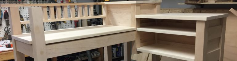
The carcass of the cabinet, made from 3/4″ baltic birch plywood
The cubby is sized to fit a set of cloth bins that we purchased on Amazon. The two bottom cubbies will accommodate taller cloth bins, the middle two cubbies can hold the shorter of the cloth bins, and the top shelf is designed to hold a row of children’s board books.
I built the cabinet carcass out of 3/4″ baltic birch plywood. This is the first time that I’ve used this product, and I have to say that it is a fantastic product. Expensive, and heavy as hell (it’s about all I can do to wrestle a 5′ x 5′ sheet of the stuff around my shop), but beautifully flat and smooth, and free of annoying voids.
Wherever two pieces of plywood meet at a right angle, I cut a dado at the table saw that is sized to accommodate the perpendicular piece of wood. This adds significant strength to the glue and screws that tie the pieces of the cabinet together. I made sure to countersink the screws so that I could hide screw holes, and cut a piece of 1/8″ plywood to form the back of the piece. The backing board sits into a rabbet, and is flush with the 3/4″ plywood that makes up the side of the cabinet.
Two oak boards, glued together to form the top of the cabinet
To top the cabinet, I glued together a couple of boards of red oak. I drilled holes for three dowels in each of the boards. The dowels help to orient the boards and ensure that the seam between them stays flat while the glue dries.
The top of the cabinet, sanded and finished with Osmo Polyx Oil
Once the glue dried, I removed the dried excess with a chisel and hand plane, gave cut the cabinet top to size, put an 1/8″ round over on the edges with a palm router, and sanded the entire thing down to 220 grit.
I used Osmo Polyx Oil as a finish. This product has become my go-to finish for hardwood projects over the last little while. It leaves a matte finish that is soft to the touch, and does not leave a plastic film or discolour the wood in the way that polyurethane does.
The cabinet carcass, pictured with the first two coats of white paint applied
Once the glue was dry on the cabinet, I cut some poplar strips and tacked them onto the front face of the cabinet to hide the edge of the plywood. Some wood filler was used to plug up the screw holes and tighten up the joinery on the face frame.
The cabinet was painted with three coats of a white latex paint. I tried to keep the coats thin and avoid drips. In between the first and second coats, I lightly sanded with 220 grit paper to remove as many brush strokes as possible. The result is a smooth, glossy finish. It isn’t quite as good as a spray finish, but for brush work, it’s not half bad.
The cabinet skirt, made from red oak, seen here prior to receiving routered edges
The last piece that needed to be built was the skirt of the cabinet, again made from red oak to match the top. The skirt consists of an inner frame that is glued and screwed together, as well as an outer frame that is glued on and sports decorative miter joints.
The cabinet skirt, sanded, routered, and finished with Osmo Polyx Oil
After the glue dried, I used my hand plane and palm sander to clean up the surface, and applied a decorative ogee profile to the upper edges. Finally, the piece was finished with a coat of the same Osmo Polyx Oil that I used on the cabinet top.
Later on in the process, I cut one of the long edges off of the skirt so that the cabinet can sit as close to the wall as possible. If I had been thinking at design time, I would have allowed the top of the cabinet to overhang the back so that it sits flush with the wall. As it stands, there’s a gap thanks to the baseboard in the nursery.
The finished cabinet, loaded with books and toys
Once the paint and finish dried, I connected all of the pieces with some #8 1-1/2″ screws. Because I expect that the oak will move with humidity while the plywood stays stable, I fed the screws through 1/4″ holes in one of the pieces so that there’s room for one piece to move without cracking.
The finished cabinet looks great in place in my son’s nursery, especially because it shares a colour scheme with the crib that I built when he was born. I’m really proud of this one.
I recently picked up a Raspberry Pi 400 for my in-laws. Having gifted them many a hand-me-down laptop over the years, I was immediately struck by the simplicity of the new offering from the Raspberry Pi Foundation, and at $140 CAD, the price point couldn’t be beat.
The box that the Raspberry Pi 400 ships in, about the size of a standard shoe box.
When the Pi arrived, I continued to be impressed by the packaging. The box contains everything that you need to get started (aside from a wall outlet and an external monitor with an HDMI input), and apart from the included mouse, all components feel well made and are pleasant to use.
Setup was simple – just plug in the power cable, the monitor, and the mouse, and the machine comes to life. Like previous iterations of the Pi, the machine boots from an SD card, and it doesn’t have a hardware power switch, so it turns on just as soon as power is connected.
The entire kit set up and plugged into a spare monitor.
The SD card comes inserted into the Pi, and is flashed with Raspbian GNU/Linux 10 (buster). On first boot, it asks for some locale information and prompts you to change the password for the default pi account, after which it downloads and installs updates.
Now, my in-laws have only just started to learn basic computer skills in the past few years. I have installed Ubuntu on the laptops that we’ve given them in the past, and I wanted the new Raspberry Pi to present a familiar user interface, so I opted to purchase a 32GB SD card and flash it with Ubuntu 20.10 to ease the transition to the new machine.
I downloaded the Raspberry Pi Imager for Windows, launched the app, chose Ubuntu Desktop 20.10 for the Raspberry Pi 400, selected the SD card to flash, and clicked the Write button.
The Raspberry Pi Imager v1.3 for Windows, pictured writing Ubuntu Desktop 20.10 to an SD card.
One of the great things about a machine that boots from an SD card is that there’s really nothing to install. I just popped the card into the Raspberry Pi, powered it on, and it immediately booted into Ubuntu.
From there, I followed the steps on screen to configure the system, installed updates, and it was ready to go.
I recently competed in the CQ WPX RTTY Contest. Well, I say “competed,” but the truth of the matter is that I wasn’t remotely in danger of winning the contest. This was my first time working with RTTY, and I spent much of the contest getting my sea legs and learning how it works.
What is RTTY?
Radioteletype or RTTY, is a digital mode that was first used by the military and newspaper industry in the early 20th century. As practiced by amateur radio operators, it is a frequency shift key (FSK) mode, meaning that the broadcast signal is comprised of a tone that is sent on one of two different frequencies. The lower of the two frequencies represents a binary 0, while the upper of the two frequencies represents a binary 1. By switching back and forth between the two frequencies at an agreed-upon rate, a radio can broadcast a string of binary data that can be decoded by whomever receives it.
The binary string that your radio sends represents text that has been encoded with Baudot code, a system not unlike Morse code that assigns a five bit representation to each character or symbol. The five bit string is padded with one start bit and two stop bits, which means that in practice, each character is transmitted as an 8 bit byte.
When first invented, a teletype system consisted of three parts: a teleprinter that displayed the messages received by the system, a modem capable of translating text to code and back, and a radio that transmitted code and received code that was transmitted by another party. In modern amateur radio setups, a computer typically acts as both the teletype and the modem, and is connected to a radio via CAT control and/or an audio interface.
Connecting the Radio to the Computer
The Yeasu FT-450D features a six pin mini din port on its back panel that is referred to as the DATA jack. Readers of a certain age will recognize this type of connector as a PS/2 mouse/keyboard jack.
This image from the FT-450D’s manual shows the pinout of the DATA jack
This DATA jack exposes pins that allow external hardware to control the radio for Audio Frequency Shift Key (AFSK) or Frequency Shift Key (FSK) operations.
To connect my computer to this port, I purchased a cable that breaks the GND, DATA IN, and DATA OUT pins out to a pair of 3.5mm audio jacks. The output jack is connected to the input of a USB sound card, and the input jack is connected to the output of the same.
My USB soundcard, a Focusrite Scarlett 2i2, connected to my Yeasu FT-450D by way of the DATA jack
It should be noted that it’s possible to build your own data cable for this radio. I opted to purchase mine, but plans are available for making a similar cable, as well as a more advanced version that can be used for other digital modes.
Configuring the FT-450D
In order to send and receive RTTY via AFSK, you’ll need to tweak a few options on the Yeasu.
Start by pressing one of the BAND buttons until you find the band that you wish to work. The ARRL band plan will tell you where to find RTTY on each. It should be noted that 30m, 17m, and 12m are called WARC bands and cannot be used for contesting.
With your band selected, press one of the MODE buttons repeatedly until the DATA indicator appears on the front panel.
Next, we’re going to dive into some of the options in the F menu. Press and hold the F key until the MENU indicator appears on the front panel, and then turn the DSP/SEL knob to find each option. Press the DSP/SEL knob to select the option, and then spin the knob to change the value of that setting. One final press of the DSP/SEL knob will save your changes. Once finished, press and hold the F key until the MENU indicator disappears.
The following need to be adjusted for each band that you wish to work:
D TYPE: Change this to USER-L, which will cause your radio to receive and transmit data on the lower sideband.
DIG VOX: When using AFSK, the radio will automatically begin transmitting when the input audio level exceeds some threshold. The DIG VOX setting adjusts that threshold. Set the output volume on your computer to a reasonable level, start transmitting a RTTY signal, and then increase the DIG VOX value from zero until the radio starts transmitting. When you stop sending the RTTY signal from your computer, the radio should stop transmitting.
RTYRPOL: This is the polarity of your RTTY signal (i.e. if the lower pitched tone is considered to be a 0 or a 1). You’ll want to set this option to NOR.
RFPOWER: RTTY is more like SSB than other digital modes. When contesting, you’ll likely want to dial your RFPOWER up to 100 if you want to be heard through the pileups.
DIALSTP: This one is optional, but because digital modes take up less bandwidth than phone, you may find it useful to adjust the rate at which the tuning knob changes frequencies.
For my first time out, I chose to use a program called MMTTY as my terminal emulator. CQ WPX RTTY is a contest, and I use N1MM+ as my contest logger. N1MM+ knows how to talk to MMTTY, which should have meant that I would be able to work the contest in a familiar environment similar to the one that I use for SSB contests.
MMTTY trying to decode a portion of the 40m band. Some digital signals are visible on the waterfall in the top right corner, but they don’t appear to be RTTY
In practice, I was late getting started with the contest, and never did figure out how to integrate N1MM+ and MMTTY. Instead, I opted to log manually, which worked well enough for my first time out.
If you opt to use AFSK and connect your radio to a sound card like I did, you will need to configure MMTTY to use the correct piece of hardware. To do this, select Option > Setup MMTTY, and navigate to the SoundCard tab in the window that appears. Use the radio buttons on this page to select the appropriate hardware for input and output.
I configure MMTTY to use my Focusrite USB (the Scarlett 2i2 pictured above) for both input and output
One started, MMTTY will attempt to make sense of whatever white noise it hears on the portion of the band that you’re tuned to.
Sweep through the band while keeping an eye on the waterfall display in the top right corner of the window. You’re looking for two peaks in the audio signal that are the same distance apart as the two vertical yellow lines. If you line the peaks up with the yellow lines, MMTTY will be able to decode the signal, and you should start to see legible text appearing in the big text box in the centre of the window.
To transmit, type a message in the lower text box and then hit your F9 key, or press the red TX button in the upper left hand of the window. The transmit button is not a toggle, so you’ll have to click it a second time (or hit F9 again) to stop transmitting once your message has been sent.
Finally, if at any time you see the word “Overflow” in the top right corner of the waterfall display, that’s an indication that the audio signal from your radio is too loud. Turn down the input volume on either your external sound card, or in the Windows sound panel until the message disappears.
What’s Next?
This coming weekend, the North American QSO Party RTTY contest (PDF) is taking place from 1800 UTC on February 27 to 0600 UTC on February 28. I intend to use this contest as an excuse to either properly integrate N1MM+ with MMTTY, or to try decoding RTTY with fldigi. Maybe both.
Going forward, I’m hoping to use my newfound skills to play with other digital modes. I may even try to contribute some code to one of the many open source projects that are maintained by hams who play on this part of the band plan.
For a few years now, I’ve been in the habit of buying myself a Lego set to build over the Christmas holidays. Most years, I pick up a Technic set, but this year, I decided to purchase the Lego James Bond Aston Martin DB5 set, item #10262.
I recently finished building the model, and was very impressed with it. This is the first traditional Lego set that I’ve built in quite some time, so I have surprisingly little experience with models like this, given that I have a large Lego collection.
I was particularly interested in the building techniques that the designers used to model all of the curves and angles on this vehicle. Throughout the build, I was thinking about how designing a set like this must be a constant negotiation between the scale of different parts. Not only does the scale of the finished vehicle have to make sense relative to the diameter of the tires, but the curves on the hood need to be appropriate relative to the overall size of the model, and there are a limited number of Lego pieces to choose from when making those decisions.
As an infrequent builder of traditional Lego sets, I was also really impressed with the construction of the set. Even elements like the vehicle’s doors that you would think are straightforward to build are actually constructed from dozens of small pieces arranged in a really clever manner to achieve the shape that’s required.
The angles that make up the dashboard, windscreen, and trunk of the vehicle are all established by connecting clips and handles together at an angle that isn’t typical to Lego. This means that many of the bricks that make up these parts are at strange angles to the body of the car, instead of everything being built parallel to the ground.
Building techniques aside, I really enjoyed building this set as a James Bond fan. A couple of years ago, my wife and I watched every Bond film in chronological order, and the Aston Martin DB5 is a vehicle that features heavily in canon. True to the films, this model has a number of sneaky spy car features, including a working ejector seat.
When my wife and I started trying to get pregnant, I began designing a crib for my child to be. My rationale was simple: my wife would be providing everything that our child needed over the course of the pregnancy, and aside from caring for her, there wasn’t much that I could do to help the process along. The crib was a project that would keep me occupied, and would provide the child with a safe place to sleep throughout the early stages of its life.
I sized everything around a mattress that we purchased from Toys R’ Us. After modelling its dimensions in Fusion 360, I could build the rest of the piece around it.
The design that I came up with was a simple affair with pleasant curves and clean lines:
A render of the 3D model that I built in Fusion 360 before starting the project
Once happy with the design, it was time to purchase the rough stock that I would mill down into the individual pieces that make up the finished crib. I chose red oak for the skeleton of the crib and poplar for the parts that would be painted white.
The rough cut stock for the project, stacked up in my shop before milling began
The Headboard and Foot Board
Each end of the crib is composed of an oak frame that surrounds a floating poplar panel. Because the panel isn’t glued into the frame, the boards that make it up are free to shrink and expand with seasonal changes in humidity.
I cut a dado along the centre of each oak piece. The dado stretches the entire length of the shorter pieces that make up the top and bottom of the frame, but on the longer pieces that make up the sides of the frame, the dado is stopped so that you can’t see it from the outside.
The oak pieces that make up the frame of each end of the crib. Shorter top and bottom pieces are on the left, while longer side pieces are on the right.
I cut a tenon that was sized to fit into the dado on the end of each of the shorter pieces. This allowed the top and bottom of each frame to slot into the sides that make up the legs of the crib. With the joinery cut, I used my band saw to cut a gentle curve along the frame tops, and dry fit the pieces to check my work.
One end of the crib dry fit with clamps. The frame is rotated 90 degrees to the left and is sitting on its side. The panels that make up the centre of the piece have not yet been installed.
Next, I began work on the shiplap boards that make up the centre panel of each end of the crib. I made these pieces out of poplar, a cheaper hardwood that takes paint well. Each shiplap board was cut on the table saw in four passes: Two to form the rabbets on each side, followed by two more to add the chamfered edges.
This is a diagram of the end of a single shiplap board. Multiple boards can be laid side by side, with their overlapping pieces interlocking to form a panel.
With the shiplap boards cut, I could slot them into my dry fit frame to make sure that the joinery was nice and snug. I think that the shiplap adds a pleasant detail to the otherwise smooth face of the end of the crib.
Four of the shiplap boards that make up the middle of one end of the crib fit into place
The Sides
With the headboard and foot board complete, I turned my attention to the sides of the crib. Each side was comprised of two long horizontal oak stretchers spanned by 13 vertical poplar bars. I cut a tenon on the end of each bar, and a corresponding mortise into each stretcher. Since there’s no such thing as a square drill bit, I used a chisel to square up each of the 52 holes.
I lost track of the hours that I spent cutting all of the joinery for the long sides of the crib. While they were certainly less complicated than the ends, the joinery was far more time consuming.One side of the crib dry fit together after all of the chiselling was completed
The Mattress Support
The final component of the build was the platform that supports the mattress. It’s a simple oak frame with a 3/4″ slab of MDF that sits inside of it.
This frame is really heavy. It turns out that Medium Density Fibreboard is super dense stuff. I’d hate to have to move a sheet of 3/4″ High Density Fibreboard!
My wife and I wanted the crib to be adjustable, with a high position that would be used until our child could sit up, and a low position that would be used thereafter.
When I built the mattress support frame, I opted to strengthen the joinery with wood screws, thinking that they would be hidden by the bottom stretcher of each side of the crib when it was assembled. Unfortunately, I neglected to think about where the frame would sit when in the high position, leaving the screws visible in the final build. Ideally, I would have built the frame the other way round, with the short ends overlapping the long ones so that the screws would always be hidden regardless of the height of the frame.
Dry Fitting the Pieces
To affix all of the pieces of the crib to one another, I opted to use threaded brass inserts and countersunk brass screws. This construction means that I can take the entire crib to pieces with nothing but a large flat head screwdriver, making it relatively easy to transport and to store once our child has outgrown it.
In a previous post, I wrote about the technique that I learned for driving the threaded brass inserts home. Even after I figured that out, accurately positioning the inserts so that they lined up with the holes that I drilled in the corresponding piece remained a huge challenge. I spent a lot of time locating and tuning these holes so that everything would line up at assembly time.
The first assembly of the crib with fasteners in place. None of the pieces have been glued together just yet, so the clamps are holding the headboard and foot board together.
While building the crib, I was also renovating the room that would become our child’s nursery. This turned out to be an equally big job that deserves its own post. Suffice it to say that I bit off more than I could chew, and didn’t manage to get all of the major components of the crib dry fit together until the day before our son was born. Thankfully, friends of ours gave us a bassinet that he slept in until I was able to finish the project.
Finish and Paint
Because of the way that the naturally finished oak and the painted poplar pieces were arranged in this build, I opted to wait until finishing was complete before gluing and of the parts together.
I used my trim router to add a 1/8″ round over to all of the parts that little fingers might be able to touch, and then sanded all of the pieces to 220 grit. Next, all of the poplar pieces were laid out on sawhorses and painted white.
The bars of the crib between coats from a rattle can
My goal was to end up with a smooth paint job, reminiscent of something that you might buy commercially. I started off using spray paint, repeatedly applying thin coats and lightly sanding between each. Although this technique worked, it seemed quite wasteful, so I switched to brushing paint on when it came time to do the shiplap. I still tried to keep my coats thin and sanded between each. Ultimately, I ended up with a smooth, almost plastic finish on all of the white painted pieces.
Once the white paint was dry, I glued everything together, and then set about finishing the oak. For this project, I opted to try Osmo Polyx-Oil satin finish. I started out applying it with a paint brush, but wasn’t happy with the number of drips and sags that I was getting, so I switched to applying it with a rag, rubbing it into the wood in the same way that you might apply furniture wax. This ensured a smooth, even coat, and left the oak feeling natural to the touch.
The two long sides of the crib with a wet coat of Osmo Polyx-Oil on the oak stretchers
Installation
By the time the crib was finally ready to be moved into our son’s room, it was the first week of November, nearly two and a half months after he was born.
Assembling the crib in my son’s nursery
Thanks to the threaded inserts and brass screws, installation was a snap. The finished crib is really heavy, and requires two people to move, so it’s a good thing that it can be easily taken to pieces.
The finished piece looks great in the corner of my son’s room. It’s far and away the nicest piece of furniture that I’ve built to date, and the fact that it was built with love for my son makes it all that much better.
Our boy trying out his new bed for the very first time ❤️